GGOV1
GGOV1 is a general governor-turbine model with electrical-power measurement, speed/load reference selection, proportional/integral/derivative governor control, load limiting, acceleration limiting, temperature limiting, actuator rate limits, turbine lag/lead dynamics, and optional diesel damping.
Warning
The damping, fuel-flow, PID, limiter, temperature, and transport-delay paths remain incomplete or unverified. The initialization below does not yet establish a consistent steady state for the smooth selector paths.
Notes
Internal control, valve-stroke, and turbine-power quantities are on the GGOV1 component base unless otherwise stated.
The dashed speed deadband block and
Dbsource field are only for GGOV1D. GGOV1 uses the speed input directly.The source diagram notes that
RupandRdowninputs are not implemented in Simulator; the equations below do not use those source fields.
Block Diagram
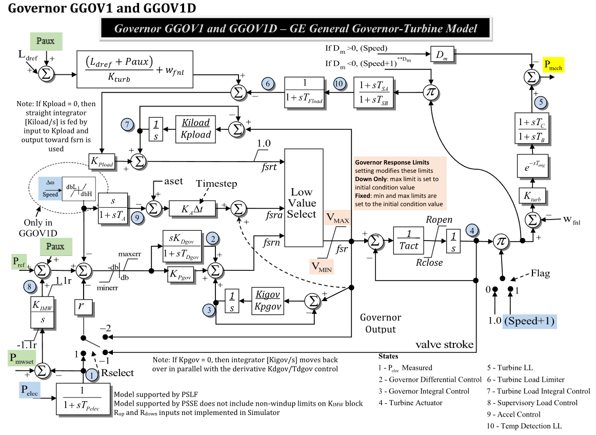
Figure 1: Governor GGOV1 model. Figure courtesy of PowerWorld
Model Parameters
Symbol |
Units |
JSON |
Description |
Typical Value |
Note |
|---|---|---|---|---|---|
\(P^{\mathrm{rate}}\) |
[MW] |
|
Optional turbine-rating power base |
0.0 |
|
\(I_R\) |
[integer] |
|
Droop feedback selector |
1 |
selects speed, electrical power, or valve feedback |
\(s_\mathrm{flag}\) |
[binary] |
|
Turbine-speed multiplier selector |
1 |
1 uses \(1+\omega\), 0 uses 1.0 |
\(R\) |
[p.u.] |
|
Permanent droop |
0.05 |
Source label: |
\(T_\mathrm{pelec}\) |
[s] |
|
Electrical-power measurement time constant |
0.0 |
State 1 in Fig. 1 |
\(e^{\max}\) |
[p.u.] |
|
Upper limit on the signed governor error |
1.0 |
Source label: |
\(e^{\min}\) |
[p.u.] |
|
Lower limit on the signed governor error |
-1.0 |
Source label: |
\(K_\mathrm{pgov}\) |
[p.u.] |
|
Governor proportional gain |
10.0 |
|
\(K_\mathrm{igov}\) |
[p.u./s] |
|
Governor integral gain |
1.0 |
State 3 |
\(K_\mathrm{dgov}\) |
[p.u.] |
|
Governor differential gain |
0.0 |
State 2 |
\(T_\mathrm{dgov}\) |
[s] |
|
Governor differential time constant |
0.0 |
|
\(V^{\max}\) |
[p.u.] |
|
Maximum governor output before actuator |
1.0 |
Governor response limits may adjust this value |
\(V^{\min}\) |
[p.u.] |
|
Minimum governor output before actuator |
0.0 |
Governor response limits may adjust this value |
\(T_\mathrm{act}\) |
[s] |
|
Turbine actuator time constant |
0.1 |
State 4 in Fig. 1 |
\(R_\mathrm{open}\) |
[p.u./s] |
|
Maximum actuator opening rate |
1.0 |
|
\(R_\mathrm{close}\) |
[p.u./s] |
|
Maximum actuator closing rate |
-1.0 |
|
\(K_\mathrm{turb}\) |
[p.u.] |
|
Turbine gain |
1.0 |
|
\(W_\mathrm{fnl}\) |
[p.u.] |
|
No-load fuel flow |
0.0 |
|
\(T_B\) |
[s] |
|
Turbine lead–lag denominator time constant |
0.0 |
State 5 in Fig. 1 |
\(T_C\) |
[s] |
|
Turbine lead–lag numerator time constant |
0.0 |
|
\(T_\mathrm{eng}\) |
[s] |
|
Engine transport lag |
0.0 |
Source label: |
\(T_\mathrm{fload}\) |
[s] |
|
Load-limiter lag time constant |
0.0 |
State 6 in Fig. 1 |
\(K_\mathrm{pload}\) |
[p.u.] |
|
Load-limiter proportional gain |
0.0 |
note path changes when zero |
\(K_\mathrm{iload}\) |
[p.u./s] |
|
Load-limiter integral gain |
0.0 |
State 7 in Fig. 1 |
\(L_\mathrm{dref}\) |
[p.u.] |
|
Load reference |
1.0 |
|
\(D_\mathrm{m}\) |
[p.u.] |
|
Diesel damping gain |
0.0 |
sign-dependent speed term in Fig. 1 |
\(K_\mathrm{imw}\) |
[p.u./s] |
|
Supervisory load-control integral gain |
0.0 |
State 8 in Fig. 1 |
\(A_\mathrm{set}\) |
[p.u.] |
|
Acceleration-control reference |
0.0 |
Source label: |
\(K_A\) |
[p.u.] |
|
Acceleration-control gain |
0.0 |
Source label: |
\(T_A\) |
[s] |
|
Acceleration-control time constant |
0.0 |
State 9 in Fig. 1 |
\(T_\mathrm{sa}\) |
[s] |
|
Temperature-detection numerator time constant |
0.0 |
State 10 in Fig. 1 |
\(T_\mathrm{sb}\) |
[s] |
|
Temperature-detection denominator time constant |
0.0 |
State 10 in Fig. 1 |
\(R_\mathrm{up}\) |
[p.u./s] |
|
Source upward ramp input |
0.0 |
Source note says not implemented in Simulator |
\(R_\mathrm{down}\) |
[p.u./s] |
|
Source downward ramp input |
0.0 |
Source note says not implemented in Simulator |
Parameter Validation
A valid GGOV1 parameter set must satisfy the following conditions:
Model Derived Parameters
The component base and flag complements are:
\(S^{\mathrm{sys}}\) is the system power base.
Model Ports
Name |
Port |
Init |
Description |
|---|---|---|---|
|
Input |
TBD |
Governor reference |
|
Input |
TBD |
Auxiliary power input |
|
Input |
TBD |
Supervisory MW setpoint |
|
Input |
TBD |
Electrical active power |
|
Input |
TBD |
Load reference |
|
Input |
TBD |
Machine speed deviation |
|
Output |
TBD |
Mechanical-power output |
Model Variables
Internal Variables
Differential
Symbol |
Units |
Description |
Note |
|---|---|---|---|
\(P_\mathrm{elec}^{\mathrm{meas}}\) |
[p.u.] |
Measured electrical power |
State 1 in Fig. 1; Source label: |
\(x_D\) |
[p.u.] |
Governor differential control state |
State 2 in Fig. 1 |
\(x_I\) |
[p.u.] |
Governor integral control state |
State 3 in Fig. 1 |
\(x_\mathrm{act}\) |
[p.u.] |
Turbine actuator or valve stroke |
State 4 in Fig. 1 |
\(x_\mathrm{turb}\) |
[p.u.] |
Turbine lead–lag state |
State 5 in Fig. 1; Source label: |
\(x_\mathrm{load}\) |
[p.u.] |
Turbine load-limiter lag state |
State 6 in Fig. 1 |
\(x_\mathrm{ldint}\) |
[p.u.] |
Turbine load integral-control state |
State 7 in Fig. 1 |
\(x_\mathrm{mw}\) |
[p.u.] |
Supervisory load-control state |
State 8 in Fig. 1 |
\(x_\mathrm{acc}\) |
[p.u.] |
Acceleration-control state |
State 9 in Fig. 1 |
\(x_\mathrm{temp}\) |
[p.u.] |
Temperature-detection lead–lag state |
State 10 in Fig. 1 |
Algebraic
Symbol |
Units |
Description |
Note |
|---|---|---|---|
\(P_\mathrm{mwref}\) |
[p.u.] |
Supervisory load-control reference |
From \(P_\mathrm{mwset}-P_\mathrm{elec}\) |
\(y_R\) |
[p.u.] |
Selected droop feedback |
Controlled by |
\(e_G\) |
[p.u.] |
Limited governor error |
After \(e^{\min}\) and \(e^{\max}\) |
\(f_\mathrm{pid}\) |
[p.u.] |
Governor PID output |
Forms |
\(f_\mathrm{srn}\) |
[p.u.] |
Normal governor fuel/stroke request |
Low-value select input |
\(f_\mathrm{sra}\) |
[p.u.] |
Acceleration-control request |
Low-value select input |
\(f_\mathrm{srt}\) |
[p.u.] |
Temperature/load request |
Low-value select input |
\(f_\mathrm{srl}\) |
[p.u.] |
Acceleration/temperature low-value select |
Lesser of \(f_\mathrm{sra}\) and \(f_\mathrm{srt}\) |
\(f_\mathrm{sr}\) |
[p.u.] |
Low-value select output |
Limited by \(V^{\min}\) and \(V^{\max}\) |
\(r_\mathrm{act}\) |
[p.u./s] |
Actuator rate-limited derivative |
Limited by \(R_\mathrm{close}\) and \(R_\mathrm{open}\) |
\(P_\mathrm{turb}\) |
[p.u.] |
Turbine power before damping |
After turbine lead–lag and transport lag |
\(P_\mathrm{damp}\) |
[p.u.] |
Damping power term |
Source label: |
\(P_\mathrm{m}\) |
[p.u.] |
Mechanical-power output |
Source label: |
External Variables
Differential
None.
Algebraic
Symbol |
Units |
Description |
Note |
|---|---|---|---|
\(P_\mathrm{ref}\) |
[p.u.] |
Governor reference |
Source label: |
\(P_\mathrm{aux}\) |
[p.u.] |
Auxiliary power input |
Source label: |
\(P_\mathrm{mwset}\) |
[p.u.] |
Supervisory MW setpoint |
Source label: |
\(P_\mathrm{elec}\) |
[p.u.] |
Electrical active power |
Source label: |
\(L_\mathrm{dref}\) |
[p.u.] |
Load reference input |
Source label: |
\(\omega\) |
[p.u.] |
Machine speed deviation |
Source label: |
Model Equations
Smooth functions: antiwindup, clamp, min.
Internal Equations
Differential
Algebraic
When \(T_B=T_C=0\), the turbine lead–lag block is bypassed before the turbine gain and no-load fuel-flow calculation.
External Equations
None.
Initialization
For a power-flow start, require \(\omega=0\) and initialize all internal derivatives to zero:
Given initialized machine mechanical power, solve the actuator and turbine path:
Initialize the limiter and control states:
These assignments assume inactive low-value select alternatives, inactive actuator rate limits, \(V^{\min}\le f_{\mathrm{sr}}\le V^{\max}\), and \(K_\mathrm{turb}\ne 0\).
Monitors
Monitor |
Units |
Description |
Note |
|---|---|---|---|
|
[p.u.] |
Mechanical-power output |
\(P_\mathrm{m}\) |
|
[p.u.] |
Measured electrical power |
State 1 |
|
[p.u.] |
Governor differential-control state |
State 2 |
|
[p.u.] |
Governor integral-control state |
State 3 |
|
[p.u.] |
Turbine actuator or valve stroke |
State 4 |
|
[p.u.] |
Turbine lead–lag state |
State 5 |
|
[p.u.] |
Turbine load-limiter state |
State 6 |
|
[p.u.] |
Turbine load integral-control state |
State 7 |
|
[p.u.] |
Supervisory load-control state |
State 8 |
|
[p.u.] |
Acceleration-control state |
State 9 |
|
[p.u.] |
Temperature-detection lead–lag state |
State 10 |
|
[p.u.] |
Normal governor request |
Low-value select input |
|
[p.u.] |
Acceleration-control request |
Low-value select input |
|
[p.u.] |
Temperature/load request |
Low-value select input |
|
[p.u.] |
Selected governor request |
Low-value select output |