REPCA
REPCA is a WECC renewable energy plant control model for inverter-coupled resources.
Warning
GridKit does not yet apply the associated generator’s Governor Response Limits
modes Down Only and Fixed to REPCA.
Notes
Note
freq is optional because the regulated bus does not yet expose a frequency
signal. With frequency control and nonzero droop enabled, omitting it holds
frequency at 1.0 p.u. and logs a warning. freq and freqref use absolute
per-unit frequency.
Block Diagram
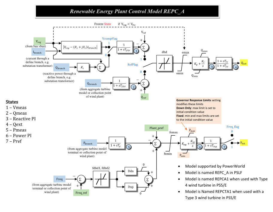
Figure 1: REPCA plant-control model. Figure courtesy of PowerWorld REPC_A model reference.
Model Parameters
All parameters are optional; omitted keys use the defaults below.
Symbol |
Units |
JSON |
Description |
Typical Value |
Note |
|---|---|---|---|---|---|
\(S^\mathrm{base}\) |
[MVA] |
|
REPCA component power base |
100.0 |
Set to the associated converter base |
\(s_\mathrm{comp}\) |
[boolean] |
|
Voltage-compensation selector |
|
|
\(s_\mathrm{ref}\) |
[boolean] |
|
Reactive-loop reference selector |
|
|
\(s_\mathrm{freq}\) |
[boolean] |
|
Active-power output selector |
|
|
\(T_\mathrm{fltr}\) |
[s] |
|
Voltage and reactive-power filter time constant |
0.05 |
|
\(V^\mathrm{frz}\) |
[p.u.] |
|
Reactive-power PI freeze-voltage threshold |
0.7 |
|
\(R_c\) |
[p.u.] |
|
Line-drop compensation resistance |
0.0 |
Component base |
\(X_c\) |
[p.u.] |
|
Line-drop compensation reactance |
0.0 |
Component base |
\(K_c\) |
[p.u.] |
|
Reactive-current compensation gain |
1.0 |
|
\(D_\mathrm{bd1}\) |
[p.u.] |
|
Lower reactive-loop deadband threshold |
0.0 |
|
\(D_\mathrm{bd2}\) |
[p.u.] |
|
Upper reactive-loop deadband threshold |
0.0 |
|
\(e^{\max}\) |
[p.u.] |
|
Upper limit on the signed reactive-loop error |
1.0 |
|
\(e^{\min}\) |
[p.u.] |
|
Lower limit on the signed reactive-loop error |
-1.0 |
|
\(K_\mathrm{p}\) |
[p.u.] |
|
Reactive-power controller proportional gain |
10.0 |
|
\(K_\mathrm{i}\) |
[p.u./s] |
|
Reactive-power controller integral gain |
10.0 |
|
\(Q^{\max}\) |
[p.u.] |
|
Maximum reactive-power command |
1.0 |
Component base |
\(Q^{\min}\) |
[p.u.] |
|
Minimum reactive-power command |
-1.0 |
Component base |
\(T_\mathrm{ft}\) |
[s] |
|
Reactive-command lead time constant |
0.0 |
|
\(T_\mathrm{fv}\) |
[s] |
|
Reactive-command lag time constant |
3.0 |
|
\(T_\mathrm{p}\) |
[s] |
|
Active-power measurement filter time constant |
0.0 |
|
\(D_\mathrm{bd1}^{f}\) |
[p.u.] |
|
Lower frequency-error deadband threshold |
0.0 |
|
\(D_\mathrm{bd2}^{f}\) |
[p.u.] |
|
Upper frequency-error deadband threshold |
0.0 |
|
\(D_\mathrm{dn}\) |
[p.u./p.u.] |
|
Down-regulation (overfrequency) gain |
20.0 |
|
\(D_\mathrm{up}\) |
[p.u./p.u.] |
|
Up-regulation (underfrequency) gain |
0.0 |
|
\(e_P^{\max}\) |
[p.u.] |
|
Upper limit on the signed active-power error |
1.0 |
|
\(e_P^{\min}\) |
[p.u.] |
|
Lower limit on the signed active-power error |
-1.0 |
|
\(K_\mathrm{pg}\) |
[p.u.] |
|
Active-power controller proportional gain |
10.0 |
|
\(K_\mathrm{ig}\) |
[p.u./s] |
|
Active-power controller integral gain |
10.0 |
|
\(P^{\max}\) |
[p.u.] |
|
Maximum active-power command |
2.0 |
Component base |
\(P^{\min}\) |
[p.u.] |
|
Minimum active-power command |
0.0 |
Component base |
\(T_\mathrm{lag}\) |
[s] |
|
Active-power command lag time constant |
3.0 |
Parameter Validation
A valid REPCA parameter set must satisfy the following conditions:
All real parameters must be finite.
The power bases and both conversion ratios must also be finite and positive;
verify() also enforces Model Ports.
Model Derived Parameters
Let \(\epsilon_T=10^{-3}\ \mathrm{s}\). Smaller time constants are raised to that floor with a warning:
\(S^\mathrm{sys}\) is the system power base; \(k_\mathrm{base}\) converts system-base
power and current signals to component base. GridKit does not expose PUflag;
these ports are always on system base.
Model Ports
Name |
Port |
Init |
Description |
|---|---|---|---|
|
Bus |
Known |
Regulated-bus voltage |
|
Input |
Known |
Branch-current real component on system base |
|
Input |
Known |
Branch-current imaginary component on system base |
|
Input |
Known |
Branch active power on system base |
|
Input |
Known |
Branch reactive power on system base |
|
Input |
Known |
Optional absolute frequency; defaults to 1.0 p.u.[1] |
|
Input |
Unknown |
Voltage-control reference |
|
Input |
Unknown |
Plant active-power reference on system base |
|
Input |
Unknown |
Reactive-power reference on system base |
|
Input |
Unknown |
Absolute per-unit frequency reference |
|
Output |
Known |
Reactive-power command on system base |
|
Output |
Known |
Active-power command on system base |
The bus and measurement inputs are required; attached inputs must be linked.
Optional references are published when attached and latched otherwise. The
qext and pext assignments are optional; both remain monitorable.
Initialization preserves qext and preserves pext only when
\(s_\mathrm{freq}=1\); otherwise pext becomes zero.
Model Variables
Internal Variables
Differential
Symbol |
Units |
Description |
Note |
|---|---|---|---|
\(V^\mathrm{meas}\) |
[p.u.] |
Filtered regulated voltage |
State 1 in Fig. 1; Source label: |
\(Q^\mathrm{meas}\) |
[p.u.] |
Filtered reactive-power signal |
State 2 in Fig. 1; Source label: |
\(x_Q^\mathrm{PI}\) |
[p.u.] |
Reactive-power PI controller state |
State 3 in Fig. 1; Source label: |
\(x_Q^\mathrm{lag}\) |
[p.u.] |
Reactive-command lead–lag state |
State 4 in Fig. 1; Source label: |
\(P^\mathrm{meas}\) |
[p.u.] |
Filtered active-power signal |
State 5 in Fig. 1; Source label: |
\(x_P^\mathrm{PI}\) |
[p.u.] |
Active-power PI controller state |
State 6 in Fig. 1; Source label: |
\(P^\mathrm{ref}\) |
[p.u.] |
Active-power command lag state |
State 7 in Fig. 1; Source label: |
Algebraic
Symbol |
Units |
Description |
Note |
|---|---|---|---|
\(V\) |
[p.u.] |
Regulated-bus voltage magnitude |
|
\(V^\mathrm{ldc}\) |
[p.u.] |
Line-drop compensated voltage magnitude |
|
\(V^\mathrm{droop}\) |
[p.u.] |
Reactive-droop-compensated voltage |
|
\(V^\mathrm{ctrl}\) |
[p.u.] |
Selected voltage-measurement input |
|
\(s_\mathrm{frz}\) |
[-] |
Smooth reactive-power PI voltage-enable gate |
|
\(e_\mathrm{RQ}\) |
[p.u.] |
Selected reactive-loop error |
|
\(e_\mathrm{RQ}^\mathrm{db}\) |
[p.u.] |
Deadbanded reactive-loop error |
|
\(e_\mathrm{RQ}^\mathrm{lim}\) |
[p.u.] |
Limited reactive-loop error |
|
\(Q^\mathrm{PI}\) |
[p.u.] |
Reactive-power PI output |
Component base |
\(Q^\mathrm{ext}\) |
[p.u.] |
Reactive-power command output |
System base |
\(e_f\) |
[p.u.] |
Frequency error after deadband |
|
\(e_P\) |
[p.u.] |
Active-power control error |
Component base |
\(e_P^\mathrm{lim}\) |
[p.u.] |
Limited active-power control error |
Component base |
\(P^\mathrm{PI}\) |
[p.u.] |
Active-power PI output |
Component base |
\(P^\mathrm{ext}\) |
[p.u.] |
Active-power command output |
System base |
External Variables
Differential
None.
Algebraic
Symbol |
Units |
Description |
Note |
|---|---|---|---|
\(V_r\) |
[p.u.] |
Regulated-bus voltage, real component |
Bus input |
\(V_i\) |
[p.u.] |
Regulated-bus voltage, imaginary component |
Bus input |
\(I_r\) |
[p.u.] |
Branch-current real component |
Signal port |
\(I_i\) |
[p.u.] |
Branch-current imaginary component |
Signal port |
\(P\) |
[p.u.] |
Branch active power |
Signal port |
\(Q\) |
[p.u.] |
Branch reactive power |
Signal port |
\(f\) |
[p.u.] |
Frequency input |
Signal port |
\(V^\mathrm{ref}\) |
[p.u.] |
Voltage-control reference |
Optional signal port |
\(P_\mathrm{plant}^\mathrm{ref}\) |
[p.u.] |
Plant active-power reference |
Optional signal port |
\(Q^\mathrm{ref}\) |
[p.u.] |
Reactive-power reference |
Optional signal port |
\(f^\mathrm{ref}\) |
[p.u.] |
Frequency reference |
Optional signal port |
Model Equations
Smooth functions: above, antiwindup, clamp, deadband2.
Internal Equations
Differential
Algebraic
Appendix A defines droop.
External Equations
None.
Initialization
REPCA reconstructs a steady operating point; arbitrary-state restart is unsupported.
Input Initialization
Internal Initialization
iclamp and ideadband2 denote the initialization helpers invertClamp and
invertDeadband, which recover inputs for the smooth CommonMath
clamp and
Type II deadband functions.
Within \(10^{-12}\) of a clamp bound, REPCA uses that
bound moved outward by \(0.1\); intervals of width at most \(10^{-12}\) return
\(\ell\). Deadband outputs within \(10^{-12}\) of zero use the midpoint; other
values are inverted by bisection.
If an initial PI output falls outside its configured limits, REPCA expands the
limits to include it and logs a warning. This matches PowerWorld’s default
Modify Limits and Run treatment of initial limit violations.
Initialization rejects an operating point if:
a required input or derived value is not finite;
the gated reactive-power or active-power PI state rate is nonfinite or does not vanish within the implementation tolerance.
Initialization is atomic; candidates are validated before state or signal writes.
Output Initialization
Monitors
Monitor |
Units |
Description |
Note |
|---|---|---|---|
|
[p.u.] |
Reactive-power command output |
\(Q^\mathrm{ext}\); system base |
|
[p.u.] |
Active-power command output |
\(P^\mathrm{ext}\); system base |
|
[p.u.] |
Filtered regulated voltage |
\(V^\mathrm{meas}\) |
|
[p.u.] |
Filtered reactive-power signal |
\(Q^\mathrm{meas}\); component base |
|
[p.u.] |
Filtered active-power signal |
\(P^\mathrm{meas}\); component base |
Appendix A: droop
where \(\sigma\) is GridKit’s smooth
sigmoid. The response preserves
\(\text{droop}(0;D_\mathrm{dn},D_\mathrm{up})=0\).