Bus
Bus represents an \(N\)-phase bus in instantaneous phase coordinates. It owns
the bus voltage and contributes the current-balance residual to
the assembled DAE. \(\mathcal{D}\) denotes the set of connected devices.
Bus voltage and its residual are algebraic when no connected model contributes
a voltage derivative; see assembly.
Block Diagram
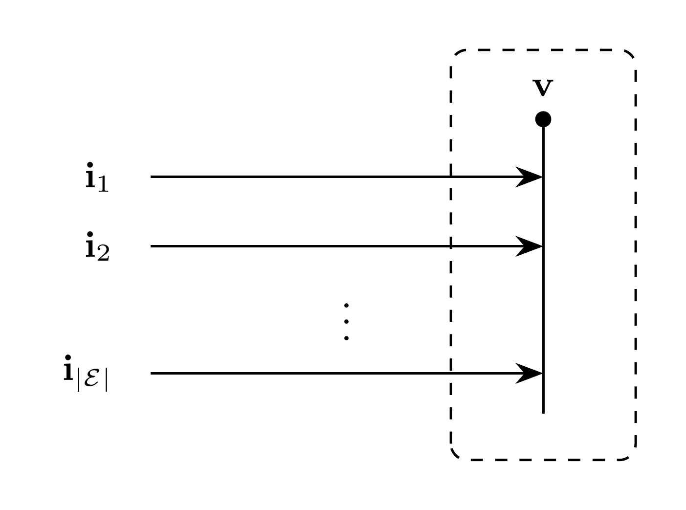
Figure 1: Bus model
Model Parameters
Symbol |
Units |
JSON |
Description |
Note |
|---|---|---|---|---|
\(N\) |
[-] |
|
Number of phases |
Required, positive integer |
Parameter Validation
Model Derived Parameters
None.
Model Ports
Symbol |
Port |
Type |
Units |
Description |
Note |
|---|---|---|---|---|---|
\(\mathbf{i}_d\) |
|
Input |
[A] |
Current from connected device \(d\) |
One port per \(d \in \mathcal{D}\), \(\mathbf{i}_d \in \mathbb{R}^N\) |
\(\mathbf{v}\) |
|
Output |
[V] |
Bus voltage supplied to connected devices |
\(\mathbf{v} \in \mathbb{R}^N\) |
Submodels
None.
Submodel Validation
None.
Submodel Wiring
None.
Model Variables
Internal Variables
Differential
Symbol |
Units |
Description |
Note |
|---|---|---|---|
\(\mathbf{v}\) |
[V] |
Bus voltage vector |
\(\mathbf{v} \in \mathbb{R}^N\) |
Algebraic
None.
External Variables
Differential
None.
Algebraic
None.
Model Equations
Internal Equations
Differential
Algebraic
None.
External Equations
None.
Initialization
None.
Monitors
Monitor |
Units |
Description |
Note |
|---|---|---|---|
|
[V] |
Bus voltage |
\(\mathbf{v} \in \mathbb{R}^N\) |