BranchBreakers
A two-terminal phasor-domain \(\pi\) branch with independently controlled circuit breakers at both terminals.
Notes
Designed for relay protection: relay
tripoutputs drivetrip1andtrip2, and relays measure the terminal-current outputs.Terminal-current outputs publish values without Jacobian coupling to the bus voltages or breaker states.
Block Diagram
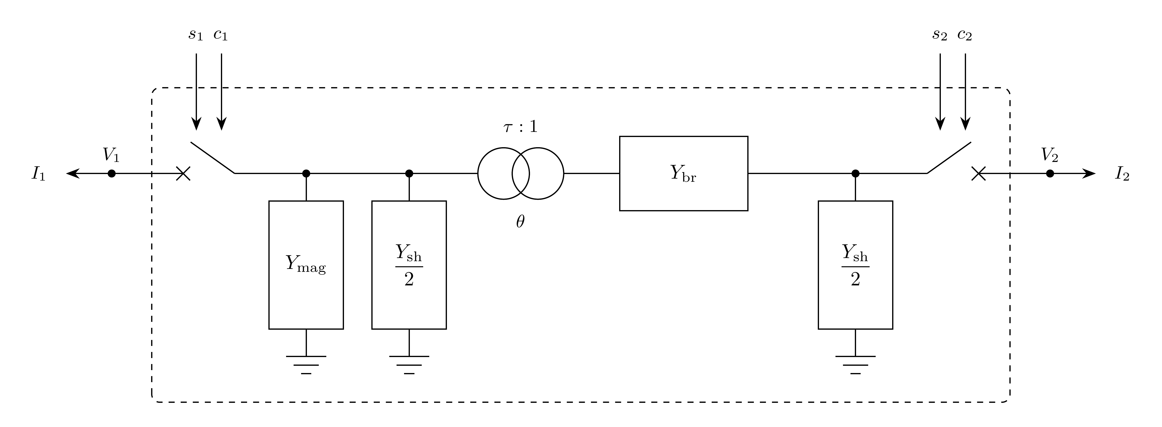
Figure 1: BranchBreakers model.
Model Parameters
Symbol |
Units |
JSON |
Description |
Typical Value |
Note |
|---|---|---|---|---|---|
\(R\) |
[p.u.] |
|
Branch series resistance |
||
\(X\) |
[p.u.] |
|
Branch series reactance |
||
\(G\) |
[p.u.] |
|
Total line shunt conductance |
0.0 |
|
\(B\) |
[p.u.] |
|
Total line shunt susceptance |
0.0 |
|
\(G_\mathrm{mag}\) |
[p.u.] |
|
Magnetizing shunt conductance at bus 1 |
0.0 |
|
\(B_\mathrm{mag}\) |
[p.u.] |
|
Magnetizing shunt susceptance at bus 1 |
0.0 |
|
\(\tau\) |
[p.u.] |
|
Off-nominal tap magnitude at bus 1 |
1.0 |
|
\(\theta\) |
[rad] |
|
Phase-shift angle |
0.0 |
|
\(T_\mathrm{brk}\) |
[s] |
|
Breaker operating time |
0.05 |
Time to \(z_k = 1/2\) for a unit step command |
Parameter Validation
All parameters must be finite real values.
Model Derived Parameters
\(Y_{mn}\) are entries of the closed-branch admittance matrix \(\mathbf{Y}\). \(Y_k^\mathrm{o}\) is the admittance seen at terminal \(k\) with the opposite breaker open.
Model Ports
Name |
Port |
Init |
Description |
|---|---|---|---|
|
Bus |
Known |
Required bus-1 terminal; the tapped side |
|
Bus |
Known |
Required bus-2 terminal |
|
Input |
Known |
Bus-1 breaker trip command |
|
Input |
Known |
Bus-1 breaker close command |
|
Input |
Known |
Bus-2 breaker trip command |
|
Input |
Known |
Bus-2 breaker close command |
|
Output |
Known |
Bus-1 terminal current, real component |
|
Output |
Known |
Bus-1 terminal current, imaginary component |
|
Output |
Known |
Bus-2 terminal current, real component |
|
Output |
Known |
Bus-2 terminal current, imaginary component |
Signal ports are optional. Attached inputs must be linked. Trip and close commands lie in \([0,1]\); unattached inputs default to zero.
Model Variables
Internal Variables
Differential
Symbol |
Units |
Description |
Note |
|---|---|---|---|
\(z_1\) |
[-] |
Bus-1 breaker closed-state latch |
|
\(z_2\) |
[-] |
Bus-2 breaker closed-state latch |
Algebraic
None.
External Variables
Differential
None.
Algebraic
Symbol |
Units |
Description |
Note |
|---|---|---|---|
\(V_{r1}\) |
[p.u.] |
Terminal voltage, real component, bus 1 |
Owned by bus object |
\(V_{i1}\) |
[p.u.] |
Terminal voltage, imaginary component, bus 1 |
Owned by bus object |
\(V_{r2}\) |
[p.u.] |
Terminal voltage, real component, bus 2 |
Owned by bus object |
\(V_{i2}\) |
[p.u.] |
Terminal voltage, imaginary component, bus 2 |
Owned by bus object |
\(s_1\) |
[-] |
Bus-1 breaker trip command |
|
\(c_1\) |
[-] |
Bus-1 breaker close command |
|
\(s_2\) |
[-] |
Bus-2 breaker trip command |
|
\(c_2\) |
[-] |
Bus-2 breaker close command |
|
Model Equations
Smooth functions: above,
below,
latch.
For readability, define:
Internal Equations
Differential
A close command drives the latch toward closed; a full trip command overrides it.
Algebraic
None.
External Equations
The real and imaginary parts are added to the bus residuals, positive entering the buses.
Initialization
All internal derivatives initialize to zero.
Monitors
Monitor |
Units |
Description |
Note |
|---|---|---|---|
|
[p.u.] |
Terminal current, real component, bus 1 |
\(I_{r1}\) |
|
[p.u.] |
Terminal current, imaginary component, bus 1 |
\(I_{i1}\) |
|
[p.u.] |
Terminal current magnitude, bus 1 |
\(\sqrt{I_{r1}^2 + I_{i1}^2}\) |
|
[p.u.] |
Active power entering bus 1 |
\(V_{r1} I_{r1} + V_{i1} I_{i1}\) |
|
[p.u.] |
Reactive power entering bus 1 |
\(V_{i1} I_{r1} - V_{r1} I_{i1}\) |
|
[p.u.] |
Terminal current, real component, bus 2 |
\(I_{r2}\) |
|
[p.u.] |
Terminal current, imaginary component, bus 2 |
\(I_{i2}\) |
|
[p.u.] |
Terminal current magnitude, bus 2 |
\(\sqrt{I_{r2}^2 + I_{i2}^2}\) |
|
[p.u.] |
Active power entering bus 2 |
\(V_{r2} I_{r2} + V_{i2} I_{i2}\) |
|
[p.u.] |
Reactive power entering bus 2 |
\(V_{i2} I_{r2} - V_{r2} I_{i2}\) |