EXAC2
EXAC2 is an IEEE Type AC excitation system with a voltage transducer, lead–lag input compensation, limited voltage-amplifier state, low-value gate, voltage regulator limits, exciter alternator state, stabilizing feedback, rectifier loading, saturation, and optional speed multiplier.
Warning
Initialization does not yet invert the smooth gates and limits used by the model equations.
Notes
Internal voltage and current signals are on model base unless otherwise stated.
The rectifier loading block \(F_{\mathrm{ex}}=f(I_N)\) is the source AC-exciter loading curve from Fig. 1; it is not a CommonMath helper.
The source diagram labels the optional multiplier input as
Speed; GridKit uses machine speed deviation, so the enabled multiplier is \(1+\omega\).
Block Diagram
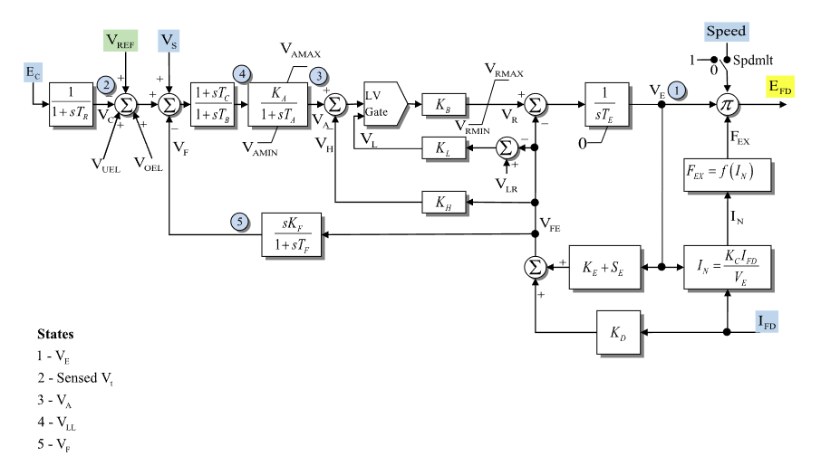
Figure 1: Exciter EXAC2 model. Figure courtesy of PowerWorld
Model Parameters
Symbol |
Units |
JSON |
Description |
Typical Value |
Note |
|---|---|---|---|---|---|
\(T_R\) |
[s] |
|
Transducer time constant |
0.0 |
if zero, \(V_C\) is algebraic |
\(T_B\) |
[s] |
|
Lag time constant for voltage-regulator input lead–lag |
0.0 |
|
\(T_C\) |
[s] |
|
Lead time constant for voltage-regulator input lead–lag |
0.0 |
|
\(K_A\) |
[p.u.] |
|
Voltage-amplifier gain |
40.0 |
|
\(T_A\) |
[s] |
|
Voltage-amplifier time constant |
0.1 |
|
\(V_A^{\max}\) |
[p.u.] |
|
Maximum voltage-amplifier output |
1.0 |
Source label: |
\(V_A^{\min}\) |
[p.u.] |
|
Minimum voltage-amplifier output |
-1.0 |
Source label: |
\(K_B\) |
[p.u.] |
|
Regulator pre-limit gain after low-value gate |
1.0 |
Source label: |
\(V_R^{\max}\) |
[p.u.] |
|
Maximum voltage-regulator output |
1.0 |
|
\(V_R^{\min}\) |
[p.u.] |
|
Minimum voltage-regulator output |
-1.0 |
|
\(T_E\) |
[s] |
|
Exciter alternator time constant |
0.5 |
|
\(K_L\) |
[p.u.] |
|
Field-current limiter feedback gain |
0.0 |
Source label: |
\(K_H\) |
[p.u.] |
|
Regulator feedback path gain |
0.0 |
Source label: |
\(K_F\) |
[p.u.] |
|
Stabilizing feedback gain |
0.05 |
|
\(T_F\) |
[s] |
|
Stabilizing feedback time constant |
0.7 |
if zero, \(V_F\) is algebraic |
\(K_C\) |
[p.u.] |
|
Rectifier loading current coefficient |
0.0 |
forms \(I_N\) |
\(K_D\) |
[p.u.] |
|
Demagnetizing factor feedback gain |
0.0 |
|
\(K_E\) |
[p.u.] |
|
Exciter field-resistance line-slope margin |
0.1 |
|
\(V_{\mathrm{lr}}\) |
[p.u.] |
|
Low-value gate lower reference |
0.0 |
Source label: |
\(E_1\) |
[p.u.] |
|
First saturation voltage point |
2.8 |
|
\(S_E(E_1)\) |
[p.u.] |
|
Saturation value at \(E_1\) |
0.08 |
Source label: |
\(E_2\) |
[p.u.] |
|
Second saturation voltage point |
3.7 |
|
\(S_E(E_2)\) |
[p.u.] |
|
Saturation value at \(E_2\) |
0.33 |
Source label: |
\(s_{\mathrm{spd}}\) |
[binary] |
|
Speed multiplier flag |
0 |
1 enables the speed multiplier |
Parameter Validation
A valid EXAC2 parameter set must satisfy the following conditions:
The saturation points follow the same two-point validation used by other exciter READMEs: both saturation values are zero, or both points define a valid positive quadratic fit.
Model Derived Parameters
The saturation curve is fitted from the two supplied saturation points. If both saturation factors are zero, use \(S_A=0\) and \(S_B=0\). Otherwise:
Model Ports
Name |
Port |
Init |
Description |
|---|---|---|---|
|
Input |
TBD |
Compensated terminal voltage magnitude \(E_C\) |
|
Input |
TBD |
Voltage-control reference \(V_{\mathrm{ref}}\) |
|
Input |
TBD |
Stabilizer input signal \(V_S\) |
|
Input |
TBD |
Under-excitation limiter input \(V_{\mathrm{uel}}\) |
|
Input |
TBD |
Over-excitation limiter input \(V_{\mathrm{oel}}\) |
|
Input |
TBD |
Machine field current \(I_{\mathrm{fd}}\) |
|
Input |
TBD |
Machine speed deviation \(\omega\) |
|
Output |
TBD |
Field-voltage output \(E_{\mathrm{fd}}\) |
Model Variables
Internal Variables
Differential
Symbol |
Units |
Description |
Note |
|---|---|---|---|
\(V_E\) |
[p.u.] |
Exciter alternator voltage state before output multipliers |
State 1 in Fig. 1; Source label: |
\(V_C\) |
[p.u.] |
Sensed compensated voltage |
State 2 in Fig. 1; Source label: |
\(V_A\) |
[p.u.] |
Limited voltage-amplifier output |
State 3 in Fig. 1; Source label: |
\(x_{\mathrm{LL}}\) |
[p.u.] |
Lead–lag block state |
State 4 in Fig. 1; Source label: |
\(V_F\) |
[p.u.] |
Stabilizing feedback washout output |
State 5 in Fig. 1; Source label: |
Algebraic
Symbol |
Units |
Description |
Note |
|---|---|---|---|
\(e_V\) |
[p.u.] |
Voltage-regulator input error before lead–lag block |
Summing junction after sensed voltage |
\(V_{\mathrm{LL}}\) |
[p.u.] |
Lead–lag output |
Input to voltage amplifier |
\(V_H\) |
[p.u.] |
Regulator feedback path signal |
Source label: |
\(V_L\) |
[p.u.] |
Field-current limiter low-value gate input |
Source label: |
\(V_{\mathrm{lv}}\) |
[p.u.] |
Low-value gate output |
Lesser of amplifier path and limiter path |
\(V_R\) |
[p.u.] |
Voltage-regulator output |
Limited by \(V_R^{\min}\) and \(V_R^{\max}\) |
\(S_E\) |
[p.u.] |
Saturation coefficient evaluated at \(V_E\) |
Uses derived saturation curve |
\(I_N\) |
[p.u.] |
Normalized exciter loading current |
Source label: |
\(F_{\mathrm{ex}}\) |
[p.u.] |
Rectifier loading factor |
Source label: |
\(V_{\mathrm{FE}}\) |
[p.u.] |
Exciter feedback signal |
Sum of saturation/resistance and \(K_D I_{\mathrm{fd}}\) paths |
\(E_{\mathrm{fd}}\) |
[p.u.] |
Field-voltage output |
Output after rectifier loading and optional speed multiplier |
External Variables
Differential
None.
Algebraic
Symbol |
Units |
Description |
Note |
|---|---|---|---|
\(E_C\) |
[p.u.] |
Compensated terminal voltage magnitude |
Source label: |
\(V_{\mathrm{ref}}\) |
[p.u.] |
Voltage-control reference |
Source label: |
\(V_S\) |
[p.u.] |
Stabilizer input signal |
Source label: |
\(V_{\mathrm{uel}}\) |
[p.u.] |
Under-excitation limiter input |
Source label: |
\(V_{\mathrm{oel}}\) |
[p.u.] |
Over-excitation limiter input |
Source label: |
\(I_{\mathrm{fd}}\) |
[p.u.] |
Machine field current |
Source label: |
\(\omega\) |
[p.u.] |
Machine speed deviation |
Source label: |
Model Equations
Smooth functions: antiwindup, clamp, min, \(q\).
Internal Equations
Differential
Algebraic
When \(T_B=T_C=0\), the lead–lag block is bypassed so \(V_{\mathrm{LL}}=e_V\).
External Equations
None.
Initialization
The machine initializes \(E_{\mathrm{fd}}\) and \(I_{\mathrm{fd}}\) first. For a standard unsaturated start, EXAC2 reads those values, sets all internal derivatives to zero, and first solves the coupled rectifier-loading equations:
Then evaluate the feedback path:
Then solve the low-value gate and voltage-regulator chain:
This standard start requires \(1+s_{\mathrm{spd}}\omega\ne 0\), \(V_E\ne 0\), \(K_A\ne 0\), \(K_B\ne 0\), inactive \(V_A\) and \(V_R\) limits, and the low-value gate selecting the amplifier path. Starts with active low-value gate limiting or saturated regulator states are outside these closed-form equations.
Monitors
Monitor |
Units |
Description |
Note |
|---|---|---|---|
|
[p.u.] |
Field-voltage output |
\(E_{\mathrm{fd}}\) |
|
[p.u.] |
Exciter alternator voltage state |
\(V_E\) |
|
[p.u.] |
Sensed compensated voltage |
\(V_C\) |
|
[p.u.] |
Voltage-amplifier state |
\(V_A\) |
|
[p.u.] |
Voltage-regulator output |
\(V_R\) |
|
[p.u.] |
Lead–lag output |
\(V_{\mathrm{LL}}\) |
|
[p.u.] |
Stabilizing feedback state |
\(V_F\) |
|
[p.u.] |
Low-value gate output |
\(V_{\mathrm{lv}}\) |
|
[p.u.] |
Normalized exciter loading current |
\(I_N\) |
|
[p.u.] |
Rectifier loading factor |
\(F_{\mathrm{ex}}\) |
|
[p.u.] |
Saturation coefficient |
\(S_E\) |